Kennicott vs. Kennecott

For those of you who think I can’t use a spell checker, I thought I should clarify something.  There really are two distinct spellings of “Kennicott” – one with an ‘i’, one with an ‘e’.

  • Kennicott refers to either the river or the glacier.  The name comes from Robert Kennicott (1835-1866), an early explorer and naturalist who made two trips to the Alaska-Yukon region (at the time, Russian America).  His first trip in 1859 was purely scientific, having been tasked with collecting specimens of animals yet unknown back east.  Given his experience in the area, Western Union hired him in 1865-1866 to lead a scouting expedition to site a telegraph line the western United States up to the Bering Strait, where it would connect with a submarine cable and a similarly long line across Siberia to Europe.  (Kennicott died of a suspected heart attack in 1866 near Fort Nurato in northwestern Alaska, and the telegraph project was never completed.)
  • Kennecott refers to the Kennecott Copper Company or the company town at the base of the mill.  The ‘e’ was a misspelling on the incorporation paperwork that has persisted in the company’s name to this day.

Honestly, the mine and the town are referred to by both spellings, and it all gets used interchangeably.  I try to be at least consistent, but I guarantee a truly pedantic editor will find me abusing that principle at least a few places on this site.

Hand-laid Track, Here We Come!

Before I left for home to be with family for Christmas, I had another point rail on an Atlas Code 55 turnout break.  The stamping process appears to leave a weak spot right where the point rail connects to the throwbar, and some of them tend to break.  This is the third of this type of failure I’ve seen, and this makes me suspicious that it may be a common problem.  Combined with my frustration at the complete lack of Atlas C55 availability, I’ve decided it’s time to make some changes.

A few hours before leaving for Iowa, I bit the bullet and ordered a #7 Fast Tracks turnout building kit and associated hardware.  I’ve heard nothing but good things about these guys and decided it was time to give it a shot.  It’s a little pricey to get started, but once I have the jigs and tools, I’ll never be beholden to any company not having track piece X in stock again.  Plus, I’ll be switching to Micro Engineering C55 flex track.  Visually it’s on par, if not a touch better, than the Atlas flex track I already have and the rail will then be identical to my new turnouts.  I don’t like the more rigid design, but it’s made in the good ol’ USA and – surprise – you can actually get it.

The kit should be waiting in the mail when I get home, but I’m still missing a few things like the files that won’t show up until tomorrow.  Hopefully by the end of the week I can actually try out building a turnout and I’ll post again with my thoughts and results.

Construction Update – 9 Oct 2013

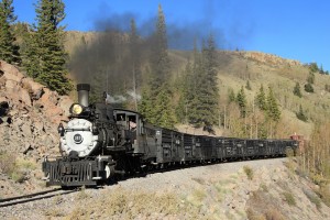
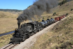
As I mentioned before, late September and early October are usually charter season here in Colorado, and consequently I spend more time out on the narrow gauge than in my basement.  So a few teasers as to what I’ve been up to, from this year’s Chama Steam trip…  (The full trip report should appear within a few weeks on my DRGW.Net website.)

charterseason2 charterseason

Okay, now that we’ve got our narrow gauge steam fix, let’s get down to what has happened on the Copper River in the past few weeks.  I’ve continued to build benchwork, becoming increasingly efficient at building and hanging open grid frames built out of dimensional plywood.  I’ve got the upper and lower track decks for Cordova (yard and harbor), Kennicott, Nicolai Junction, and McCarthy finished and hung on the wall.  Plus, I’ve migrated the old yard piece onto the new benchwork at Cordova, and placed the rest of the plywood sheet down for the other half of the yard.

I also built a new set of shelves in my workshop area (on the backside of the wall from the Cordova dock or Kennicott), and on one of those is the Cordova reverse loop.  It’s really the first real track laid explicitly for my CRNW.  I’m not counting the old recycled Fort Nelson yard, since it’s, well, recycled.

In addition, I decided to hang some decent fluorescent light fixtures.  Even though they won’t be used for operating sessions and the like (that’ll be handled by the under-benchwork LED strip lights), they make working a joy.  The basement really feels like less of a dingy hole when it has adequate light.  The fixtures are just 2-bulb T8 Lithonia SB232120GESB fixtures from Home Depot.  They’re actually pretty nice – for $32, you get a decent fixture with a high power factor electronic ballast (important to me, given that I’m going to be loading my poor 15A lighting circuits right up to limit eventually) and a tough wraparound diffuser.  I looked at fixtures from all the home improvement stores and a bunch online, and I’m very happy I settled on these.   Bulbs – for now – are just whatever I had lying around.

And now, pictures showing benchwork construction…

Atlas, Where’s My Code 55?

As many of you N scalers know, Atlas has had some significant problems with their Chinese suppliers when it comes to their track products.  Some of their Code 55 stuff has been out of stock for over a year.  Dates I’ve seen posted for when stuff is “supposed to arrive” come and go.  The C55 flex was supposed to be here in August, but yet it’s late September and nobody has any in stock.  I’m becoming more concerned by the day that I’m going to be benchwork complete by the end of the year and Atlas still won’t have their act together.

Micro Engineering makes a fine product right here in the USA.  ME unweathered flex comes out to about $0.1322/inch, whereas Atlas works out to $0.1000/inch when bought through the likes of MB Klein in 100 piece lots.  I don’t mind the price difference, honestly – that’s not what holds me back.  I like the free-flexing nature of Atlas C55 better.  I find that it makes for much more even curves without kinks. I like the longer Atlas turnouts – particularly the No 10s.  And, at the end of the day, I want my ties to all match in terms of spacing and texturing.  I don’t want a mix-and-match of track vendors from a visual point of view.

I’m mostly just ranting.  I have a lot of woodworking to do before I’m ready for more track than I already harvested off the old layout.  But if we get into December and there’s still no Atlas track, I’m going to have to start strongly considering a wholesale switch of vendors or even going to handlaid.

Another Update

‘Tis September, and that means it’s travel and photo charter season in my world.  So layout progress has been slow.

On Sunday, I tore down the old helix, stripped away the ever-precious Atlas Code 55 flex track, and then cut the remainder up into little chunks that went to the trash.  I also hung the first two open grid frames, and they look good.  Very solid, very straight, and awesome to put roadbed and track on.  I think I’ll still add a couple L-brackets underneath just to give them some strength.

I also found a piece of plywood as I was cleaning that was perfect for an extension around my workbench.  I’d always planned to have a branch coming off the top deck (from the reversing loop at Nicolai Junction) around the bench so that I could test engines/cars/electronics without actually going out to the layout.  Plus it will make a decent staging track for trains coming on/off the branch.  So, that was cut out and installed last night, and I’ll add track to it in the next couple of days.  Last night I just laid two pieces of cork and a salvaged piece of flex on it, so that I could hook up the command station for the first time in years and actually see something move.  Actually seeing the SD60M that will become CRNW 600 move a few feet was a very rewarding and motivating experience!

No pictures this time, but maybe later in the week as I get more things cleaned up and put into place.

Weekend Progress

Given that yesterday was Labor Day here in the US, I spent the day labouring on building benchwork.  The result was ripping three sheets of maple furniture plywood down into 0.75″x3.25″ and 0.75″x4″ dimensional members, and cutting three pieces of drywall that will separate the workshop from the layout area.

Why maple?  The short version is that all of the fir plywood we could find at the usual home improvement stores yesterday was severely warped.  Not just in one dimension, but twisted in both dimensions.  AC-grade fir was $44/sheet, and all twisty.  Good maple plywood was $50/sheet, and flat as could be.  For 6 bucks a sheet, I decided to go with flat.  The side benefit being that I’m going to have some rockin’ awesome looking benchwork that nobody will ever see once I get the layout up.

The first construction to go up will be the section under Cordova and McCarthy, then the peninsulas out to Kennicott and the Cordova wharf, and then we’ll start building along the back (east) wall.  Once I can put the start of the Cordova yard back in place, I’ll be able to clean out the rest of the room and make space to actually construct the rest of the framing.  Until then, all of the construction is being done in the garage by kicking the cars out for a few hours.

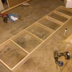
Here’s the first piece of open grid support, which will go under Cordova.

grid1-small

Eureka!

I’ve been pondering and worrying how to actually build the open grid that will form the foundation of my benchwork since I started tearing down the old stuff over a month ago.  My old theory was build the stuff to survive WW3, and then oversize by a bit.  Okay, maybe that’s an exaggeration, but I think mountains of 2x4s were some significant overkill for the problem.

My new approach, as suggested by many other modelers, is to use good 3/4″ AC plywood ripped into dimensional strips.  My working theory is to build an open grid where the back will be 4.25″ tall, while the front and cross-members will be 3.25″ tall.

The cross-members will be drilled with several (2-4) 1-1/4″ holes for wire routing towards the front and bottom, and will also have four pocket screw holes drilled.  (I was introduced to the Kreg pocket hole jig earlier this week by Michael Petersen.  It was one of those things that as soon as I saw it in action, I knew I had to have it.  It’s the blue thing in the pictures below.)  Then, using wood glue and a 90 degree clamp, we’ll build up the grid.  Once each piece of grid is built (probably in the garage), it’ll be hauled downstairs and installed on the layout.  The back will be held to the 2x4s with one pocket hole screw and one direct (horizontal) screw.  The lowest level will also likely get a 2″x2″ leg every four feet or so.

The grid will be sized such that the outside dimension, front to back, is 1-1/2″ shorter than the planned finished dimension.  This provides room to attach a 2″x2″ chunk on the front every 16″ or so, and the fascia will eventually mount to these.  That leaves plenty of space for installing switches, indicator lights, cab bus plugs, etc. between the front dimensional member and the hardboard fascia.

I tried building a short piece of this tonight just as a test, and it went spectacularly well.  I’ve included a few pictures from the test.  I’ve got some Iowa Scaled work to do this weekend, and a photo train on the San Luis Central on Sunday, but hopefully I can get some benchwork construction done somewhere in there.

Proto-Freelancing: The Third Copper Crossing

The Copper River & North Western crossed the Copper River three times on its way from Cordova to the mines at Kennicott – once across the delta on miles and miles of trestles, fill, and the occasional truss bridge, once at the famed “Million Dollar Bridge” near Miles Glacier at milepost 49, and then again northeast of Chitina at milepost 132.

Both of the lower crossings were permanent and relatively durable.  The miles of temporary trestle were slowly filled with rock where possible, making for a very sturdy embankment between more permanent trestles and spans.  The Miles Glacier bridge stands to this very day as a testament to its engineering and construction, although it did need a few million in repair work in the past decade to undo 1964 earthquake damage that dropped the last span into the water.

The last crossing, however, was never permanent.  The CRNW built the Cordova-Chitina line to a slightly better standard than the Chitina-Kennicott line, because it initially considered the latter segment to be a branch line off of a mainline that had ambitions of reaching further into the heart of Alaska.  (That, of course, never happened.)  Due to the expense of yet a third large steel bridge on what, at the time, was considered a branch, the MP132 crossing was constructed as a timber trestle with steep approach grades on both sides.  Each year the spring break-up of ice (and sometimes due to glacial lake outflow flooding – more than once a year) would take out significant portions of the bridge, and each year, CRNW B&B forces would drag out the pile driver and put it back.

What actually happened was that the 1938 trestle (the one that carried the last train on November 11, 1938) washed out in the spring ice break-up of 1939, just as expected.  It was replaced by a cable tramway high over the Copper River, which lasted into the 1960s.  In 1971, the current deck girder road bridge was completed roughly where the trestle was located, and the grade was turned into a slightly less primitive road.  The road was improved again in the 1990s, giving us the state of the McCarthy Road today.

Alternate History

Now stepping into the world of the CR&NW that only exists in my mind at the moment, and is turning into reality in my basement…   The CRNW has survived into the present day, and is still hauling ore from expanded workings around McCarthy.  Clearly some rinky-dink trestle that gets destroyed a couple times a year is not going to have survived this long.  The third bridge would have been built at some point in this alternate history – but when?

It’s likely that no bridge would have been built during the WWII era due to material shortages.  Either it would have been built in the 1930s – not likely because of the low demand for copper due to the Depression and cheaper copper available from other Kennecott properties – or in the late 1940s/early 1950s following the war.   Given that Kennecott dieselized (or electrified) many of its steam properties immediately following WWII, it’s reasonable to assume that a surviving CRNW would have followed suit.  So, for our alternate CRNW history, we’ll just say that diesels, mine improvements, and track improvements were all part of a large capital project starting around 1951, as the light rail, untreated trestles, and other such would have been in need of renewal and improvements by this point to keep the railroad safe and efficient.

Okay, so now we’ve worked out an approximate date that would be likely for construction of the Chitina bridge.  Thanks to an engineering diagram that Ron Simpson posted on the myLargescale.com forum (full-size image here) a couple years ago, I know what the original proposed (1909) Chitina steel bridge would have looked like.  The planned structure would have a 360′ Pennsylvania truss crossing the main channel on the Chitina end, followed by three 275′ deck truss structures similar to those used on the Kuskulana bridge.  The railhead would have been approximately 94ft. off the river bottom over the main channel, and 70ft. off ground level on the east end of the bridge.  We’ll take this as the baseline.

I’m torn on how to model this.  On one hand, I know what the planned structure was supposed to be.  On the other hand, the railroad lived with the temporary trestle until 1938, and per the reasoning earlier, that temporary structure may well have lived until the very early 1950s.   If a 1950 engineer was looking at the same river, would he arrive at the same conclusion as the 1909 engineer who came up with the original structure?  Or, instead, would the 1950 engineer look to newer, less time consuming and costly construction styles, such as deck girder?  Would that bridge have lasted to present day?  Just to throw another complication in there, would the State of Alaska still have built a road out to McCarthy?  Okay, okay, let’s start working through those one by one..

Various bits of data I can find from the USGS and other qualified organizations suggest that the immediate Chitina area has not received any earthquakes violent enough in the last 60 years to have significantly damaged a large, well-constructed bridge like the one proposed.  It’s simply been too far from various epicenters of large quakes (1964, 2002, etc.)  Given that railroad bridges are typically designed for 100+ year lifespans, there’s no reason that a 1950 bridge should not still be in service today.

Given other large-span railroad bridges built in the 1950s and 1960s, I have to assume that some form of truss would still be the preferred methodology.  (The Wisconsin DOT bridge manual for railroad structures still lists “truss” as the preferred type for spans over 150 feet, even in 2003.)  As for which exact truss style would be used, that’s still up in the air.  I could match the rest of the railroad and use a Pennsylvania for the through truss design, but I

I have to assume that either Kennecott or the State of Alaska would have eventually connected McCarthy into the road system rather than being completely dependent upon rail access.  If Kennecott had built the access road, then the only logical choice is to share the road/rail bridge at McCarthy.  If the state built it, then it’s still an option.  Public data shows that even the 1971 highway bridge that exists today only saw 166 cars/day on average in 2000, and 400+ cars/day today.  That’s pretty low to justify a multi-million dollar bridge.  (I admit, I’m biased on this point.  I’ve wanted to model a joint road/rail bridge ever since seeing the combined BC Rail bridge at Fort Nelson decades ago, so I’m totally justifying myself here.)

My current thought is to go forward with the original bridge design, selectively compressed to fit within the 5 feet of allotted space that I have (the real one would have been around 8 feet), but make it a shared road/rail deck .  It’ll obviously be one lane, so we’ll add some traffic lights at both ends, and interlock them with the signal system.

It does raise the question, however – if the road and railway shared the MP132 bridge, what would they do when crossing the Kuskulana?
Weekend Update – Aug 24-25

Unfortunately I haven’t accomplished as much this weekend as I’d hoped.  I’ve spent most of my time getting projects ready for Iowa Scaled Engineering’s next printed circuit board run.  Some bits were model railroad-related, but most of it wasn’t.  So I don’t even have any cool new toys coming up that I can tell you about.

But hey, our first ad in Model Railroader appears in the October issue, which should be to subscribers shortly.  I’m excited and hopeful that this will help get us a bit more attention.  Seriously, if you’re considering servo switch motors or networked fast clocks, at least give us a look.  The more time I can justify working on model railroad-related projects, the faster the CRNW gets done…

I finally found that one pesky screw still holding the panel that will become the new Cordova yard to the 2×4.  So, upon removing it and cutting one metric crap-ton of wires, I pulled the two sections of plywood out and stored them on the other side of the room.   Then I removed what was left of the old industrial-strength benchwork (heavy 2x4s), the rest of the staging yard, and more wiring.  So now I’m down to bare wall framing again.

The next step – hopefully tonight or tomorrow – is to start noodling how open grid benchwork will attach to the wall frame.   I’ll probably build a couple prototypes, but I want to very quickly get to building benchwork on the wall frames that are complete.  You see, I have too much stuff “in storage” in the basement, and the shelves it sits on are in the way of Chitina.  So the faster I get the base benchwork built, the faster I can slide some storage shelves under it and get stuff in the way, well, not in the way.

CRNW LED Lighting, Round 2

While I was in Indianapolis, I received a call from DHL…  They had a box from China, and I hadn’t been home for the first two delivery attempts.  Woohoo!  The LEDs for lighting the layout arrived (all 500 feet of warm white and 250 feet of cool white) early!

When I arrived back in Colorado (which turned out to be a long and annoying tale on its own – thanks a lot, United…), the other piece of the puzzle was in the mail – an RGB LED strip.  As you’ll recall, my plan was to combine two warm whites, a cool white, and an RGB strip, so that I can vary both the intensity and color of layout light.  Eventually, I plan to integrate that with the fast clock system so that over the course of an operating session, the light will change to model the real change in daylight.

While I want to get going on benchwork again this weekend, I couldn’t go get more lumber because it’s (quite unusually) pouring rain outside and I loaned my truck to a friend.  So, given that I had some power MOSFETs and a MRB-GIO sitting around, I decided to try building a prototype MRBus light controller.  Turns out it was pretty darn easy, aside from some thinking about correct snubbing on the FETs to prevent inductive kick from killing them.  I’ll post a schematic soon, but for now, I’ll show some pictures of the prototype.

In the pictures, you’ll see the MRB-GIO, the breadboard with the power drivers and snubbers, my trusty Lambda power suppy, and then the test LED strip, showing all the different ways it can be turned on and dimmed.  Then there’s also a couple photos of some early tests – I could just send intensities over MRBus to the controller, and lights would change.

This is going to work beautifully…