Author Archives: ndholmes

Basic Benchwork Nearing Completion

I realize it’s been nearly two months now since I’ve added an update, but I’ve been rather busy.  For most of May I was actually out of the country, bumming around Germany, Belgium, and the Netherlands for fun and profit (or at least work…)

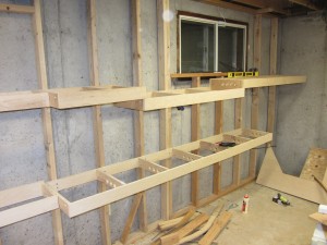
After getting back, I’ve been working on benchwork and more planning.  The upper valance deck is now all the way around the layout, the middle deck is complete right up to the Chitina Town Lake (where the helix will connect it to the lower level / Abercrombie Canyon area), and the lower deck is complete through the Miles Glacier Bridge.

None of what’s left concerns me all that much, except for the helix.  Helices and I have some uncomfortable history.  My last attempt – while functional – took about four times longer to build than I wanted, wound up being rather expensive, and lacked a certain something in dimensional stability.  This time I think I’m going to go with the threaded rod approach to spacing the decks, rather than trying to screw them all into a semi-rigid wood frame.  Stay tuned…

Weekend Update

There’s not really that much to add – it’s the last weekend before taxes are due here in the US, so I’ve spent much of my weekend working on paperwork.  Ugh.

I did get to the layout for a few hours today and managed to install the gridwork for the upper valance along the walls with Kennecott / McCarty / Cordova.  It’s identical to the track level gridwork except for the lack of crossmembers.  I’m only installing a crossmember every 4′.  The grid doesn’t have to support much weight, except for the light strips and their cables.

The one gotcha is that the grid will have to cross the two windows.  I don’t want to block them, as they serve as secondary exits from the basement in case of fire or other emergency.  So I think what I’ll do is stop the grid on either side, and just have a magnetically-attached front board over the window area.  As long as I make the wiring harness so it also separates easily, this will preserve the use of the windows in emergencies.

In the process of putting the grid together, I got fed up with some of the scrap plywood I had sitting around.  So I also cut out the subroadbed for the Eyak yard area.  That consumed most of the remains of the sheet and got it out of my way in the process.

Lighting & Benchwork Update

Those of you who have been following along know that one of the core electronic pieces I’ve been working on for the CRNW is an LED lighting system tied into the fast clocks.  Over the run of an operating session, I want to transition from “dark” (really dim blue light) through the brilliant warm light of daybreak, the bright white of midday, and the through the golden hour and sunset back to dark.    The system will consist of the fast clocks – obviously – as well as a MRB-GIO to figure out color and intensity, and then a set of power booster boards that actually control the 2000W going to the LED strips.  The power boosters will be local, each controlling <20ft of layout, to keep the amount of power being switched to a more manageable level.

The prototype power booster boards for the LED lights showed up a couple weeks back, but this weekend was really the first chance I’ve had to try integrating them with the full system.  I connected one up to my test LED strip and mounted it back over Cordova, and then connected it to a MRB-GIO and did some basic programming to turn it into a lightning controller.

Results are promising – I need to do a bunch more tweaking on the exact light transitions, but my first try came off pretty well.  I also did a few tests using a bunch more strips to increase load.  The system was designed for up to 6A per channel, so I cranked it up to around that.  Heating was actually less than I expected – the board only slightly warm to the touch even switching 6A on a couple channels.

I’ve posted a few photos of the new power control board, as well as some samples of midday, evening, and night light.  Night isn’t that bright, I promise.  It’s just the camera evened out the exposure.

On the benchwork front, I did get the top deck extended from Strelna over to the north end of the Chitina yard.  The bottom deck is still being pondered – I’d really like to add a short Katalla Branch as a very low level.  The problem is that I can’t figure a way to shove a helix under where the junction should be.  I’m contemplating a train elevator along the wall (hidden behind the Miles Glacier Bridge area), since trains to/from the coal fields above Katalla would be short – 6-8 cars plus power.  Regardless, I’m still pondering it.

Oh well, off to Memphis for the week tomorrow.  I’ll figure out what I’m doing about a potential Katalla branch train elevator when I get back.

Benchwork Update

Just a quick note to say that progress is finally being made again.

Last Thursday, I ripped two more sheets of 3/4″ plywood to replenish my dwindling supply of plywood dimensional lumber.  It’s really remarkable how quickly building benchwork grid goes through a supply of the stuff.

This weekend, I’ve spent significant type tackling building the benchwork itself.  The result is that the grid is now complete from Kennecott through Strelna on the upper deck, and Cordova through mid-Alaganik (where it turns the corner) on the lower deck.

One of the things of note is the large gap for the Kuskulana River bridge.  My layout includes four of the railroad’s most notable big bridges – Miles Glacier, Chitina (third crossing of the Copper), Kuskulana, and Gilahina.  Three of the four are selectively compressed, but the Kuskulana crossing will be done to scale.   That means 238 scale feet of depth from railhead to water, or about 18 inches.  Fortunately, the deep vertical part of the canyon is only about 170′ across at the water line, and about 190-200′ at the rim.   The larger bowl sort of depression of the valley is about about 775′ across, or just under 5 real feet in N scale.  The CRNW spanned the gap using 2x 150′ deck trusses (one on each side) and a 225′ deck truss over the main canyon.  Then there was another 250′ of trestlework to connect the steel bridges with the grade.

Here’s a couple pictures from when I visited back in 2009 that illustrate the main chasm and the bowl-shaped valley it cuts through:

And finally, here’s the piece of benchwork that will eventually support the model canyon – yes, it seriously impinges upon the bottom deck, but it’s the only place I do this, and it’s to make a significant visual element that everyone familiar with the line will recognize.

That’s all for now, folks.  Hopefully I’ll have the gridwork done in a couple more weeks and be on to sub-roadbed.  After that, we’re on to track!

Ever Seen a CR&NW Train Order?

While this site is largely about my fictionalized present day CR&NW in N scale, make no mistake – I have a great interest in the history of the real thing as well.  It’s just one of those railroads that really captures the imagination.  Because the line existed in such remote country, was essentially a company railroad, and existed for such a short time, I’ve never found many relics of the real thing.   In the last few weeks, however, I’ve managed to pick up some of that operating paper.

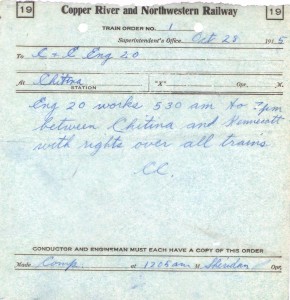
So, how many of you have ever seen an authentic CR&NW train order?  Well, here you go…  This one was written to engine 20 on October 28, 1915, allowing it to work between Chitina and Kennecott from 0530h to 1900h.  It’s absolutely amazing to me that a flimsy piece of train order paper from almost 100 years ago has survived to this day in spectacular condition.

crnw-trainorder

I’ve got a few more things from these finds as well – blank train order forms, agent’s ticket stubs, and a couple clearance forms.  Truly amazing stuff.  I’ll post the rest in the near future.

Cordova’s Docks

I’ve been working on a post about the alternate history that lead to my present-day version of the Copper River & Northwestern, and as part of that I was justifying the changes in Cordova.  I realized that my section talking about dock changes was getting so darn long and detailed that it might as well be broken out into its own post.

Specifically, one of the things I’ve contemplated since first imaging this railroad is, “How does the ore actually move out of Cordova, and in what form?”  The Good Friday Earthquake of 1964 provides some pretty good cover for whatever I chose to do – the quake caused land deformations and a moderate tsunami by the time it reached Cordova.  Contemporary news reports indicate that the docks were all but destroyed, and as such I’m assuming that if the CR&NW were still operating, it would have been required to rebuild its dock facilities.  As tragic as this event was in the real world, it’s like a get out of jail free card for the modeler.

Now, here’s the question – what sort of dock facilities would the railroad rebuild?  When the CR&NW was actually operating, the ore was so rich (or could easily be concentrated) to the point it could be economically shipped in sacks and pallets to the smelter in Seattle.  Eventually, Kennecott installed a concentrator to be able to process lower grade ore (but still insanely rich, by today’s standards).  Assuming the mines had survived, concentrators would have been increasingly necessary, as would using solvent extraction – electrowinning (aka SX-EW, basically dissolving copper and electrically plating it back out) to process the tailings and even lower grade ore.  There would have been no way to ship these low grade materials to the lower 48 economically for processing, so I have to assume increased processing would have been set up somewhere along the route – likely some concentration at the mine and some down the line, where there was more space, better access to power, and more hospitable weather conditions.  (Plus, it’s now in the middle of what’s now a national park.  I would hope that even in the 1960s and early 1970s before Wrangell-St. Elias was founded, there was enough sense to not bury such a unique and wild landscape in giant leach piles, but I’m probably hoping for too much on that one.)

How much copper and concentrate are we really talking about?  Let’s just go overboard for fun to see what the upper limits would be.   We’ll use a large open pit copper mine with a dedicated rail haul system – ASARCO’s Ray Mine  and Hayden concentrator-smelter complex in Arizona – as a sort of upper bound on what we might be dealing with.  The place is absolutely huge, but isn’t even in the top 10 as far as largest copper mines.  It cranks out 300+ millon pounds of copper from Hayden and 75+ million pounds of copper from SX-EW directly at Ray.  If you assume that’s all refined before it’s shipped, that’s only 187,500 tons, and at 100 tons/car and 365 days in a year, 5 railcars per day.  So let’s say that we only refine that to 50% concentrate before shipping.  It’s still only 10 railcars per day, or 1000 tons.

Looking through the various categories of oceangoing bulk vessels, we’d probably want something in the “Handysize” class if we were going to ship copper ore.  These range from 10000 to 35000 tons of DWT capacity.  So, assuming 50% concentrate, that means we’d have a vessel calling in Cordova roughly every 20-30 days to load up if we went with a bulk transport system. Not bad.  That’s a realistic call schedule for something running to the west coast of the lower 48.

However, this overlooks a few factors.  The US no longer has copper smelters anywhere on the west coast.  Currently, the only copper smelters operational in the US are ASARCO at Ray, AZ, Kennecott at Magna, UT, and Freeport McMoRan at Miami, AZ.  Canada only offers us one more – Xstrata’s smelter in Rouyn-Noranda, Quebec.  There’s nowhere for our bulker to offload to, except to transload onto rail again.   Also, I’m assuming that my “modern” Kennecott mine on the CR&NW wouldn’t produce anywhere near the output of Ray used in the example above.  Probably more like 200 tons of pure copper or 400 tons of 50% concentrate every day.  (That’s still 146 million pounds per year, which puts it in the middle of the pack for US copper mines.)   In addition, building a pure bulk loader doesn’t account for other inbound supplies that come by rail (mine supplies, fuel, etc.), outgoing non-ore freight (such as sulphuric acid from smelting, timber products, etc.), or even outgoing electrolytic copper from SX-EW processes.

Now our dry bulk freight isn’t looking so good.

The ARR has received car-float service from the west coast for years.  The ARR receives roughly one carfloat a week at Whittier, with a capacity of 50-ish cars per trip, plus the stacks of containers on top.  Certainly a surviving variant of the CRNW could do something similar.  So, given the ability to skip transloading, it seems like a rail barge slip would likely be the answer to the CRNW’s shipping problems.  50 cars per week is a bit tight, though, so we might have to have some extra capacity added on in the summer.

Besides, one ship a month sounds boring.  I’m a model railroader and this is my model railroad, after all, so I get to make some executive decisions about things that might not be the most economically plausible, but make my alternate reality a whole lot more interesting.  Having a removable rail barge that my operators have to load/unload in some prescribed order has a lot more potential challenge for my crews.  Otherwise, it’s just run the ore transport trains through a loadout loop and head back to the concentrator.  Again – boring…

That’s not to say the docks would have vanished entirely.  Cordova still today has a thriving fishing industry, and I presume the canneries would have also rebuilt in short order after the quake.  Rail service along the cannery dock would have provided them with incoming materials along with the ability to ship our refrigerated cars full of frozen fish.  (For perspective, Trident Seafoods lists their Cordova cannery as capable of processing 1.8 million pounds of salmon… daily!  That’s 900 tons of fish.  Even assuming only 10% of that is frozen, that could still be 1-2 reefers or 2-3 refrigerated containers a day!  Fresh would still need to ship via air freight, as a rail barge would need 5-6 days to reach the west coast terminals.)  So in my Cordova, there will be a wooden wharf area with a built-in siding, next to the barge slip.  Running frozen fish in reefers to distribution points in the lower 48 sounds like a reasonable proposition, or at least gives me some more operational possibilities.

So, that’s my rationale behind only providing Cordova with a 4 track barge slip and no bulk loader.  Bear in mind that I do air freight for a living, so my grasp on oceangoing bulk transport may be missing some key points.  If anybody who reads this has actual experience in these industries, I’d appreciate hearing from you.

Also, hopefully I’ll get back to actually building the railroad this week and have a progress update by the end of the weekend. Between being overwhelmed with work and feeling kind of off for the last month, I haven’t accomplished much lately.

CRNW LED Lighting, Round 3

Honestly I got almost nothing done this weekend in terms of benchwork.  Nearly all of my efforts went into other, non-model railroad tasks and then into working on the LED lighting system a bit more.  I’m running another set of boards soon, and wanted to get enough groundwork done to get the LED driver boards into this batch.

Tasks left to accomplish were as follows:

  1. Work out mounting to layout and characterize thermal/electrical parameters in operation
  2. Solve the inductive ringing problem in the LED drive
  3. Plan how lighting control would be distributed and design power control board

Task 1:  Mounting Considerations for LED Lighting

Some time back, roughly when I started benchwork construction, I found some great T-shaped galvanized steel drip edge (intended for roofing) at Lowes.  Strong due to its folded shape, light, wouldn’t rust, metal (to provide some heatsinking and protection between a potential high current short and the wooden benchwork), and cheap ($~4 for a 10 foot strip when I bought it), it seemed the ideal material.  Plus, the folded edge would reflect light back towards the layout and away from the aisles.  I put a single strip in with one of my lumber purchases, and it’s been sitting in my garage for the last four months.

Today, I cut off a four foot section of the stuff, since that matched the LED strips on my test piece.  Using a thorough coating of Loctite 300 heavy-duty spray adhesive (I’d previously tried my usual go-to adhesive – 3M 77 – and was underwhelmed), I laid out the four planned LED strips on the steel -warm white #1, RGB, cool white, and finally warm white #2.   Each strip was harvested from the original test 2×3 board, so these have been used a number of times now…
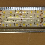
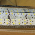
An end view, including the electrical tape used to insulate the exposed ends A look straight down The four strips - warm white, RGB, cool white, and warm white 2

With the strip prepared, I then mounted a thermocouple to the top of the steel to monitor the temperature.  Using a bar clamp, I attached it to the layout (in the usual test position, over what will become the Cordova yard someday) and powered it up with an old bench supply.  Ambient temperature at this point was about 23C (73F). Current was approximately 3A for 3x 4′ strips of white being lit simultaneously.

I left the lights alone for an hour as I did other things, so that I could see where the temperature would stabilize.  Turns out, the answer is at approximately 45C (113F).  The steel was warm to the touch, but the strips were notably cooler after an hour of running then when they were mounted to a piece of wood.  It looks like the heatsinking works!  LED longevity is closely linked with temperature, and once you pass an operating temperature of 50C, things start going downhill in a hurry.  45C for three strips running at 100% (more than I plan to run in actual operating conditions – my plan is currently at most 2 at 100%) is pretty darn good.
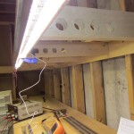
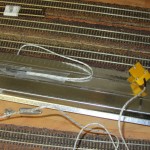
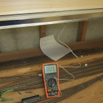
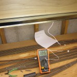
The temporary LED strip mounted up on the benchwork with a clamp.The thermocouple on the back of the steel mounting plate.Initial temperature - 23C Final stable temperature - 45C

One interesting note – the operating current at 45C had increased to 3.3A.  This makes sense – bandgap of LEDs decreases with increasing temperature.  So, with less voltage drop across the LEDs, the ballasting resistors (56 ohms total, split into two 1206 resistors – see more about this later) allow more current.  So, as a note, LED strip lights appear to have a 10% current rise over the 20C between room temperature and operating temperature.  Almost all of that additional power will be dissipated in the resistors, so it’s not even going into providing useful light.  (See analysis in the final section.)

Task 2:  Fix the Inductive Ringing
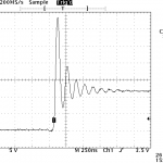
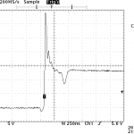
The drain side of the FET with an undamped loadWhen I initially investigated doing variable LED control for layout lighting, I noticed some reasonably nasty inductive spikes whenever the MOSFETs controlling the strips would shut off. The screen capture from my scope on the right is a pretty typical kick – the FET shuts off, and the drain side of the FET would ring up up obnoxiously high voltages.

Since I’m only planning on using FETs with a 30-40Vds rating, these spikes could easily turn into circuit-killers.  Plus, they’re likely radiating lots of electromagnetic noise that will cause other issues down the line when I have 100+ amps of LED strip lights running and switching on and off.
2.5A with a FR155 diodeMy initial hope was that a freewheeling diode from the drain up to the+12V rail would solve my problems.  I was operating under the assumption that my problem here was inductance in the LED lines, and that if I gave the current somewhere to go, my problem would go away.  At low currents, it looked promising, but as I started pushing 2-3A through my test setup, I got the waveform on the left.  Better (less ringing), but still with the 30+V spike before the diode got going.  All I had on hand for reasonably quick diodes were some old FR155s.  While great at reverse recovery time, I can’t find a spec on how fast they go into forward conduction.  Regardless, a decent Schottky diode should beat them hands down.  I just don’t have one to try.
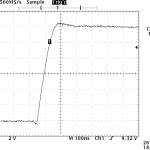
22nF damped from drain-sourceAn alternate approach I tried was to damp the system by applying a small capacitor between the FET’s drain and source.  As little as 22nF was enough to significantly clean up the waveform, and 0.1uF damped it out completely.  I don’t like the idea of a capacitor in there, though, because this will almost certainly need to be quasi-matched to the parasitic inductance in the lights.  I’m going to try a faster diode first and see if that fixes my problem.  If that doesn’t work, however, we’re back to some sort of RC snubber circuit.

Task 3: Plan a Lighting Control Scheme

Safety in designing this light system is paramount.  Given that the layout will consume at most ~150A of current to run the lighting (at 12V, but 150A is still a lot of I2R heat in any short or questionable connection), fuses in all the right places are a key design feature so that any failure doesn’t end catastrophically.

Per measurements taken at steady-state in the test fixture, any of the white strips are going to take 0.275A/ft at 45C.  The RGB strip will need approximately 0.1A/ft for each of the three channels lit.  So, figuring on an absolute maximum of three full strips (all three whites) on at any given time, I’m looking at 0.825A/ft maximum.

My initial plan had been to use larger modules, controlling as much as 30A through a single control board.  However, that means larger FETs, larger freewheeling diodes and snubbers, and larger wires everywhere, since any potential short may have to soak up 30A @ 12V until the fuse goes.  Given our 0.825A/ft metric, a 30A module would feed ~35 feet of layout lighting.  The heavy wire that I would need to handle any possible shorts over such lengths quickly showed this as an impractical approach.

If I used the 10ft length that the steel flashing comes in as a module length instead, that’s 8.25A per module, maximum.  That’s nicely under a 10A fuse by a decent safety margin, and most wiring that I would use could handle 10A for a short overload period until the fuse went out.  (Mini-ATO blade fuses like I’m considering using will blow in <0.75s at 135% of their rating.  So 13A would take it out in less than a second.)

My current plan is modules for every 10ft section, with one single input fuse of 10A.  Each board will then have 6 N-channel FETs (likely 3x AO4882 duals), 6 FET drivers (likely MCP1416s), and six optocouplers, along with dual RJ45s for the control bus (one in, one out).   A single Cat5 cable will run around the layout, delivering signal ground and 6 light PWM channels from a main lighting control board to the optoisolated inputs on each booster node.

I have the schematic done, but it’s already pushing 2300h and I’m tired.  Have to go to that real job tomorrow, so I should probably get some sleep and put the board off for another day.

Addendum:  LED Strip Lights and Voltage

As sort of an interesting side research project, I decided to investigate more about the relationships in LED strip lighting between input voltage, power dissipated in the two ballasting resistors, and power actually delivered to the LED lamps themselves.  Some of my discussions earlier in the day with a friend had made me wonder what the relationship really was between these three things.

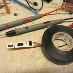
Step one was to just cut off a piece and decapsulate it so that I could get probes right on the pins.  Not really that hard – with a little encouragement, the coating peeled right off.  I then powered it up and realized that having three death rays shining in my eyes as I was trying to probe was going to be a real problem.  So, I used a trick I learned long ago when dealing with warning lights on cars that shouldn’t be on but inexplicably were: grab the electrical tape and – poof – no more annoying light!
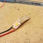
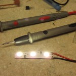
led-strip-decapsulate led-strip-owmyeyes led-strip-better

Internal construction of these strips (nominally rated 12V) consists of a 27 ohm, 1206-package resistor (rated for 0.25W of dissipation) between +V and the first LED, then three LEDs in series (each “LED” being a 5050 package with three LED die inside in parallel), and then another 27 ohm resistor to ground.

Procedurally, it was just a matter of punching each voltage into the power supply, measuring the voltage across one of the resistors, and plugging the result into a spreadsheet.  Given the input voltage and voltage across one resistor, I could calculate the current through the circuit, and thus the drop in both resistors and consequently the power that must be dissipated in the LEDs themselves.

Here’s a pair of graphs of the results.  The first is just power burned in each type of component – blue being resistors and orange being LEDs.  In the second graph I stacked them, so that you can see how large of a percentage of the total is burned off as unproductive ballast resistor losses at high voltages.

Power dissipated in the resistors vs. the LEDs for various input voltages A stacked graph of resistor/LED power, to give you a better idea of their relationship as part of the total draw

It really makes me wish for a constant-current design, but I realize the additional complexity that would entail.  Cheap constant-voltage LED strip is cheap – custom engineering my own is expensive.  Darn.

Framing Completed

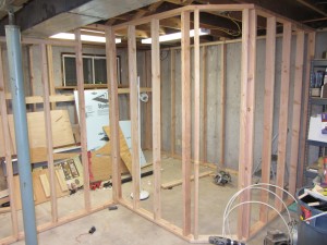
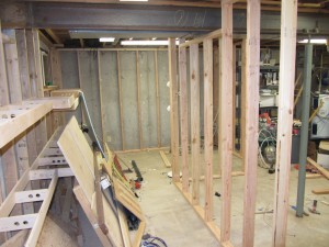
As of earlier this afternoon, I’ve actually completed all of the 2×4 framing that will hold up the CRNW.   Now I need to complete the grid and roadbed, and then I can get down to fun stuff like trackwork again.

The first shot is looking at what will eventually be the Chitina Yard on the top level and Abercrombie Canyon on the bottom level.  The second shot is looking down the long straight-away, with Gilahina on the top rear, Eyak on the bottom left rear, Alaganic on the bottom right, and Strelna on the top right.

The next problem is to either use or junk everything in my extra lumber pile.  I had to move it up against the completed grid in order to install the framing, but now I need to either use it or junk it as it’s in the way.  Once I get that solved, then I’m nearly out of ripped dimensional plywood lumber, so I need to make more.  The problem is that it’s damned cold outside in the winter, and as you can see, there’s not much room to run 4’x8′ sheets through a table saw in the basement anymore.

crnw-framing-complete-1 crnw-framing-complete-2

Smells Like Progress

While not feeling the greatest this weekend, I resigned myself to the basement and building benchwork.  As a result, the gridwork is now in place for Cordova-Eyak on the bottom level and McCarthy-Gilahina-Chokosna on the upper level.

Included in the upper level is the first major piece of depressed grid that will accomodate one of the four big bridges I plan to model  – the Gilahina Trestle.  (Photo linked from Don Bains’ Virtual Guidebooks site.)  The other three big bridges being the Miles Glacier / Million Dollar Bridge, the third Copper River crossing, and the Kuskulana Bridge.)  The current version is actually the second trestle – the original burned in 1916 and was replaced by the one we have today.  The structure is ~880 feet long and ~90 feet high on a ~15 degree curve (radius ~440ft.), with six piles per bent and extensive cross-bracing.  Today, it survives alongside the McCarthy Road in a deteriorated state.

For my proto-freelanced version of the CRNW, though, there’s simply no plausible way the trestle would have survived in service to present day.  A 100 year old high wooden trestle is just not up to the passage of heavy ore trains and 200-ton locomotives multiple times per day, no matter how well built or well maintained it may be.  Plus, the trestle forms most of a very sharp curve – much sharper than any reasonable mainline standard.  However, it’s such a stunning visual element along the line, and one that many people who have visited the area are familiar with, so I also can’t leave it out.  My solution is that the mainline will pass by in the foreground, atop a modern deck girder bridge constructed as part of a 1960s-70s era line change (exact date in alternate history to be determined), while the old abandoned trestle remains in the background.  Like many things in the wilderness of the far north, the old is often left just because it’s not economical to tear it down.  Plus, in this case its historical significance to the area in addition to its site within the the Wrangell-St. Elias National Preserve would lend to its preservation.

I’ve had to scale the Gilahina Trestle just a bit.  While 880′ in length, it’s only about 650′ on a straight line between the ends due to the sharp curvature.  (Distances estimated from aerial photographs.)  At full size, it would be approximately 4′ long and 6.75″ high in N scale.  I plan to keep it full height – hence the drop section to give me an extra 3.25″ to play with, but compress the length to about 3′, or 480′ in full size.

If anybody has measurements or plans for the Gilahina Trestle, I’d greatly appreciate hearing from you.  Otherwise I’ll have to head back north and spend some quality time with just me, the trestle, a tape measure, and an ultrasonic range finder.

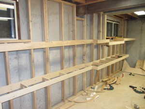
Here’s a couple shots of the new benchwork grid, including the drop section for accomo

benchwork-eastwallbenchwork-eastwall2

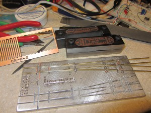
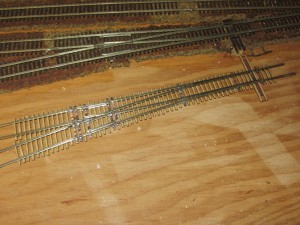
In addition, the Fast Tracks jig finally arrived, and I’ve been practicing at building turnouts.  So far, I’ve built two – one right and one left – and I don’t think I’ve quite gotten the hang of it yet.  Both are usable, but not quite as perfect as I’d like – particularly in the area of getting the point rails just right and making the throwbar move flawlessly.  (I seem to always get the point rails stuck on the stock rail when soldering them, and can never get it deburred once I separate them.)  Also, the FT#7 is a bit bigger than the Atlas #7, leading me to believe the Atlas #7 is really more of a #5-#6.  I’ve put my second attempt next to an Atlas unit so you can do a size comparison.

fasttracks first-scratchbuilt-turnout

Until next time…

Happy New Year!

Like any good model railroader, I spent New Years Day in the basement working on the layout.  I was hoping my Fast Tracks jig would arrive on New Years Eve, but alas, it did not.  So, I reverted to working on lighting, benchwork, and some electronics design.

The good news is that the entire layout room now has proper room lights – nine fluorescent 4′ dual T8 fixtures, to be exact.  It makes it much less of a dingy hole in the ground and much more a presentable layout room.  Now if only the construction disaster would clean itself up…

As far as benchwork, I accomplished a piddly 32″ – the upper deck between McCarthy and the Kennicott River crossing.  The electrical took longer than expected, and I needed to accomplish some design work  for Iowa Scaled for a new optical track detector we’re working on.

My goal for the rest of the week is the rest of the east wall (McCarthy to Kuskulana on the upper and Cordova to Eyak on the lower) and – if the stars align – the rest of the wall framing and clean up some of the random junk in the way of progress.  We’ll see what actually happens.